
 تويت
تويت

جهاز استشعاري مشرح شبيه لسكان ماستر هديه لاعضاء قدماء وان شاء الله تجدون الفائده
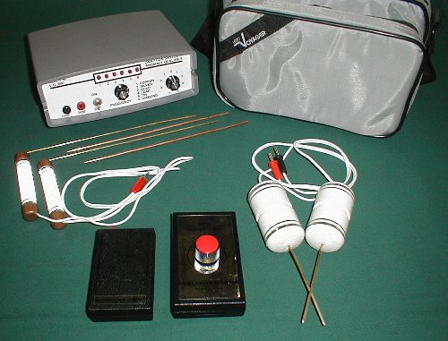
Fig. 1: Complete VR-800.
The VR-800 is a so-called long-range locator (LRL) made by Dell Systems of Haines City, FL. LRL's are a class of devices that claim to have the ability to locate certain things from a distance, usually 100's of feet up to miles. Most, if not all, utilize dowsing rods or a similar swivel-mounted dowsing device to make the indication during use. The VR-800 is no exception, and comes with a pair of dowsing rods in addition to the main transmit box, ground probes, and two small, belt-mount units. Fig. 1 shows all the components.
The theory of LRL operation is to transmit a signal into the ground that will excite the distant buried target. A "signal line" is established between the transmitter and the target, and the dowsing rods are used to detect and track the signal line. Because the receiving half of the VR-800 is just a pair of simple dowsing rods, it stands to reason that the transmitter half somehow justifies the suggested retail price of $1995. Let's start with a look at the transmit box.
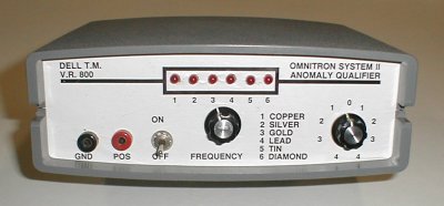
The face of the transmitter is shown in Fig. 2. There is a power switch, a 6-way target (frequency) selection switch with corresponding LED's, a fine-adjustment knob, and a pair of signal output jacks. On the back side is a battery compartment which holds 4 C-cells. The 6-way switch selects the transmit frequency for copper, silver, gold, lead, tin, and diamond. The fine-adjustment knob further varies the frequency, although there is no clear indication as to what the numbers around the knob mean. Assuming that the "0" position is a nominal setting, then fully counter-clockwise ("4") is a minimum adjustment and fully clockwise (also "4") is a maximum adjustment. The frequencies (in Hertz) were found to be:
Nominal Range
Copper 295 275-336
Silver 466 417-577
Gold 612 530-817
Lead 787 656-1169
Tin 487 433-610
Diamond 550 482-710
The inside of the transmit box is shown in Fig. 3, with the inside of the front panel in Fig. 4. Besides the switches and LED's on the front panel there is a hand-wired circuit board glued to the bottom half of the box, shown in Fig. 5. The circuit board used is known as "perf board", a type normally used for prototyping circuits and commonly available at Radio Shack. The circuitry is a "555" timer chip wired as a pulse oscillator with 6 trim potentiometers that set the frequency, depending on which is switched in by the front panel switch. A complete schematic is shown in Fig. 6 - the unmarked potentiometers are 100k that are adjusted to achieve the final frequencies.
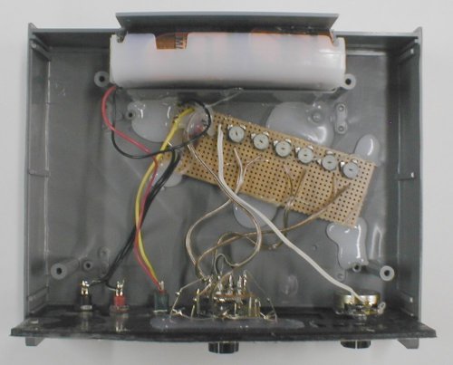
Fig. 3: Inside of the transmitter unit.
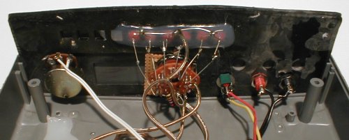
Fig. 4: Inside of the transmitter front panel.
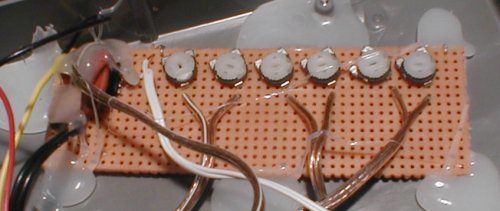
Fig. 5: Transmitter circuit board.
Fig. 6: Schematic.
The 555 pulse output is connected to one of the output jacks through a decoupling capacitor, with the other jack connected to the circuit ground. The decoupling cap has the effect of blocking DC while still allowing the pulse to go through. The pulse duty cycle is very large, around 95%, meaning that 95% of the time it is in a "high" state and 5% of the time it in a "low" state. Because of the decoupling capacitor and the extremely short pulse width, the output signal appears to be nearly zero most (95%) of the time, with short negative-going pulses. Thus, the RMS signal (effective signal power) delivered to the ground probes is exceedingly small, around 1 volt rms.
The analysis so far has been for unloaded (open-circuit) ground probes. In operation, the ground probe wires are plugged into the panel jacks, and the probes are inserted into the ground. The probe wires are made from common zip cord, which is separated enough so that the probes can be inserted into the soil no more than 8 inches apart. Depending on moisture, the soil will resistively load the transmitter outputs. This will have two effects, one being that the decoupling capacitor will interact with the resistive load to cause severe signal decay and distortion. The second is that the 555 timer chip alone is not designed to drive much of anything, and the output pulse is further degraded by the chip's inability to drive the ground resistance (there is no drive amplifier in the VR-800).
Dell Systems claims the VR-800 utilizes "Harmonic Induction Technology" (HID), and the advertising claims that frequency selection is "micro processor" controlled and can be "reprogrammed" for other elements. In fact, the manual for the "Weight Chek" accessory (described below) says of the HID concept: "This [Harmonic Induction Discrimination technology] was an extremely light "Micro Processor" with only three basic components, a computer chip, a timer, and a selector and the secret of being able to program the chip with the timed, synchronized transmission of frequencies of any chemical element... [It] produced three (3) timed frequencies responding to the electron, neutron and atomic weight of the element."
The use of the word "Harmonic" implies that the transmitted signal contains harmonics - this is basically true, since a pulse does have significant harmonic energy. The term "Induction" implies that the transmitted signal inductively couples with the target in some manner, which gets back to the idea of signal lines as mentioned above. But the notion of generating a signal line - with the fundamental frequency and/or any of its harmonics - to a distant target is false. Even if signal lines were not pure fantasy, with only the 555 driving closely spaced ground probes through a decoupling capacitor, the delivered output power is negligible. The claim that a "micro processor" is used to control frequency selection is entirely false; there is no microprocessor or computer chip, or anything that even remotely resembles one. The claim that there are 3 timed frequencies responding to the electron, neutron and atomic weight of the element is also false. There is only one pulse waveform, therefore only one fundamental frequency, plus its mathematical harmonics, all of which have nothing to do electrons, neutrons, or atomic weight (there is no such thing as a "neutron frequency" anyway).
The pulse frequency, as mentioned before, is variable over a wide range of values for any given setting of the element selector switch. Interestingly, there is quite a bit of overlap in the frequency ranges, further debasing the claims that the MFD frequencies are tuned to the resonant frequencies of certain elements. For example, on this unit the adjustment range for gold (530-817 Hz) overlaps the ranges for silver, lead, tin, and diamond. There is no way to know what frequency is being transmitted regardless of what the selector switch is set to.
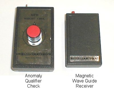
Fig. 7: Belt units.
I mentioned two belt-mount units - they're shown in Fig. 7 and both require a 9v battery. The first is what Dell Systems calls an "Anomaly Qualifier Check" (AQC), or "Weight Chek". It has a 1/8" headphone-type jack that the rods plug into via wires, a power switch, LED, and potentiometer. The inside of the AQC unit is shown in Fig. 8, and the schematic is almost identical to the main transmitter except there is no 6-position switch. Instead, the frequency is set only by the adjustment knob so it has a continuous frequency adjustment. Also like the transmitter the output signal is capacitively coupled so at least there is no danger of shorting the rods together and damaging the circuit. When the unit is turned on the LED blinks, but not at the same frequency as the output pulse. Apparently the LED is a self-blinking type.
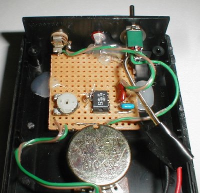
Fig. 8: Inside the AQC.
The advertising claims that the AQC is used to null out weak target signals, thereby eliminating "micron-sized" (invisible) gold particles. It says it can also be used to determine the size of a target, by progressively turning the knob until the rods cease to respond. The adjustment knob is only calibrated as "Ounces" and "Pounds" so I'm not sure know how you would read the position. The Weight Chek manual has some other interesting claims. It says "Weight Chek cycles 92 of the commonly used frequencies within the KHZ range then senses and locks on to the frequency used by the MFD." This is entirely false - the unit outputs a pulse whose frequency is set by the user; it does not "cycle 92 frequencies," it does not sense anything the MFD is doing, and it does not lock on to the MFD transmit frequency.
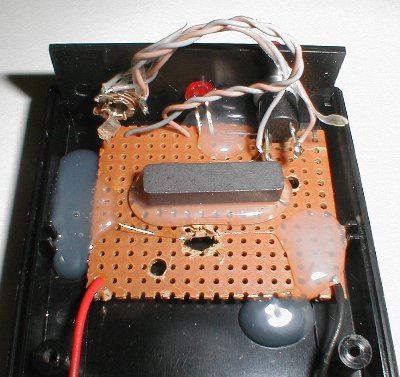
Fig. 9: Inside the MWGR.
The other belt-mount unit is called a "Magnetic Wave Guide Receiver". Like the AQC, it has a 1/8" headphone jack that the rods plug into; it also has a momentary push-button switch and an LED. When you push the switch, the LED turns on. The inside of the Magnetic Wave Guide Receiver is shown in Fig. 9. Besides lighting the LED, the only thing the switch does is short the dowsing rods together. If you touch the dowsing rods together, the LED also turns on. I'm not sure why the user of the VR-800 needs a battery powered box to short the rods together, or why he would need an LED to tell him that the rods are shorted. A final interesting feature of this unit is the bar magnet that is glued inside the box. It is not connected to anything, or seemingly used for anything, just sitting there. There are no advertising claims I've been able to find on this accessory, so I cannot comment on what it's supposed to do, other than to say it doesn't do much.
The remaining pieces of the VR-800 are the ground probes and the dowsing rods, as well as a carrying case. The ground probes are shown in Fig. 10, along with one disassembled. They are made of common PVC pipe fittings and 1/4 brass rods. It is obvious that the quality of construction is extremely poor and can easily be exceeded by any reasonably competent handyman. The dowsing rods are shown in Fig. 11 with an inset showing details of the inside of the handle; these are made from common copper pipe and fittings, plus 1/4" brass rods. Again, poor quality is evident and better rods can easily be made for very little money.
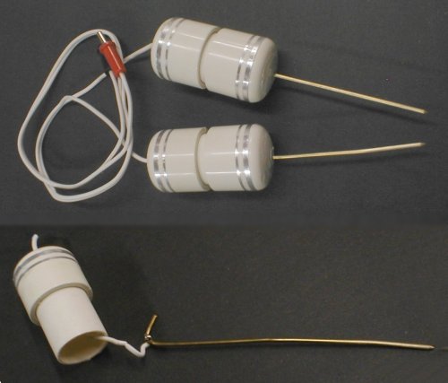
Fig. 10: Ground probes.
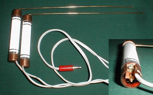
Fig. 11: Dowsing rods.
Dell Winders, owner of Dell Systems, maintains a web site (/url]) with some discussion forums for LRLs. One of those forums is for "product reviews", so I posted my findings on the VR-800. Dell replied that basically he was unaware what circuitry was inside the VR-800 even though he was selling them with his name on them. But he then admitted that a later unit, the "GS Pro", has essentially the same circuitry as the VR-800.
As for cost, the VR-800 currently retails for $1995. This particular unit was originally purchased for $1675 with the AQC unit costing an extra $595, for a total of $2270. The circuitry in the transmitter, including all the LEDs, pots, and switches for implementing 6 frequencies, but excluding the case, can be built for about $12 with parts from Radio Shack. I was unable to price the exact case but a similar sized case from Radio Shack is $8. The Weight Chek unit can be made for about $10, including the case. The Magnetic Wave Guide Receiver can be made for $6 including the case. Using commonly available hardware from the local home improvement store, the L-rods and ground probes will cost about $8 for materials. So the entire setup can be made for less than $50.
In summary, the VR-800 is an extremely poor design with amateurish construction. The transmitter outputs a signal which radically changes with soil conditions and does not have the capacity to drive the signal to anywhere near the claimed distance of 1 mile. Even adding an output power amp and matching the output impedance to the ground will only result in signal transmitted for maybe tens of feet, not miles. The frequency setting is arbitrary and has no meaning. The Weight Chek unit is of similar poor design and does not even come close to doing what is claimed of it. The Magnetic Wave Guide Receiver is just a shorting switch and serves no apparent useful function. In the end, most, if not all, of the technical and performance claims of this unit are blatantly false.


