
 تويت
تويت

جهاز استشعاري مشرح من الداخل هديه لجميع اعضاء قدماء
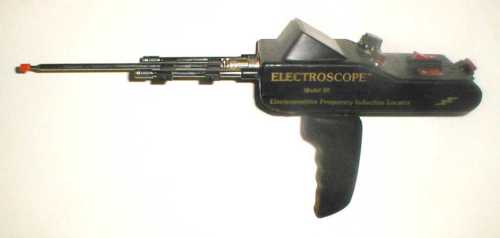
Fig. 1: Electroscope Model 20.
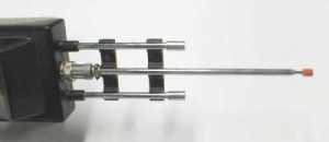
Fig. 2: Antennae configuration.
In the world of long-range locators, Electroscope is arguably one of the best-known names around. This is because Electroscope had a prominent advertising presence in the early-to-mid 1990's. It is very likely that more Electroscopes have been sold than any other brand of long-range locator.
Originally, Electroscope had two models: the 20, and the 301. The 20 was the more basic of the two, and is shown in Figure 1. It consists of a control box mounted on a swivel handle, with three collapsible antennae (Figure 2). The main controls (see Figure 3) consist of a knob labeled "DISC.", and a rocker switch with settings labeled "All Metals Mode" and "Gold Silver Mode". There is a battery check button, and two more slide switches, both only labeled with the embossed words "ON OFF." There is an LED next to the Disc knob, and the bottom of the handle includes a 1/4" headphone-type jack for plugging in accessories. The Model 20 uses a 9-volt battery. It continues to sell for the original price of $695.
The control box is molded plastic, which has a very poor quality finish. It appears to be amateur-made, and has some embossed labeling that does not appear to correctly correspond with the actual controls that are mounted. The handle is also molded plastic, with a nice ergonomic shape. The knobs and switches are labeled with extremely poor-quality adhesive paper labels, which do not hold up well at all.
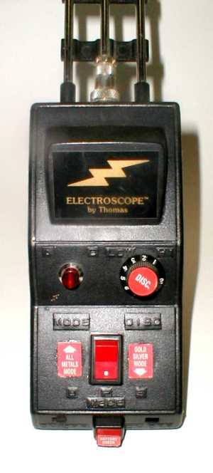
Fig. 3: Top view. The embossed labels don't match the red stickers.
How It Works
To use the Model 20, the user extends the antennae, turns on the switch, and holds the handle such that the overall device is fairly level. The general claim for these type devices, is that the upper unit (box and antennae) will swivel and point the way to treasure. The mechanism by which they supposedly work varies amongst manufacturers, but those that involve electronics usually claim to transmit a signal that excites distant treasure which, in turn, creates an attraction to the antennae. The manual for this device does not discuss specific theories, nor have I ever seen any theories put forth by the manufacturer, in any advertising or articles. In fact, the manual and most of the ads never make any claim that the Electroscopes will even locate treasure, or anything else for that matter. They are mostly devoid of any claims of performance, or even purpose, leaving it to the consumer to assume what the purpose of the device is.
Looking Inside
Opening the Model 20 requires first removing the adhesive labels on the sides. This is easily done with no damage to the labels. The plastic case has upper and lower halves glued together, and separating them without damage takes a little patience, but is not too difficult. Inside, the expected hook-up for the controls consists of a phenomenal amount of wiring, all of it solid "Bell" type wire, all of it of the same color. Besides that, the main items of interest are two epoxied modules, one toward the front and one toward the rear. There is also a liberal amount of hot-melt glue used, which seems to be a common theme with LRLs (along with horrendously bad soldering). Figure 4 shows the overall interior, and Figure 5 is looking forward at the antenna connections.
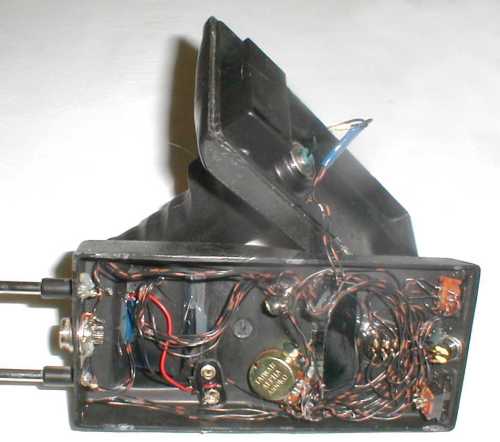
Fig. 4: An inside view.
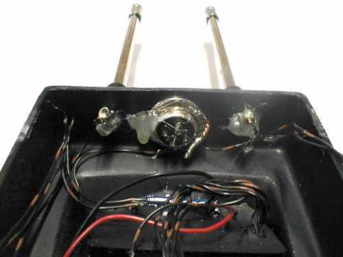
Fig. 5: Looking forward. Note the liberal use of hot-melt glue
It is impossible to trace out any of the wiring because most of it, at some point, goes into the modules. It is obvious that the excessive use of same-color wire, along with the epoxied modules, is meant to deter any attempt to reverse-engineer the device. But, practically all epoxy can be dealt with, using heat and solvents, and the epoxy used in the Model 20 is no exception. Before dissolving the epoxy, all wiring was desoldered from the controls and each wire labeled. At this point, the epoxy modules and the entire wiring harness could be removed from the case. See Figure 6.
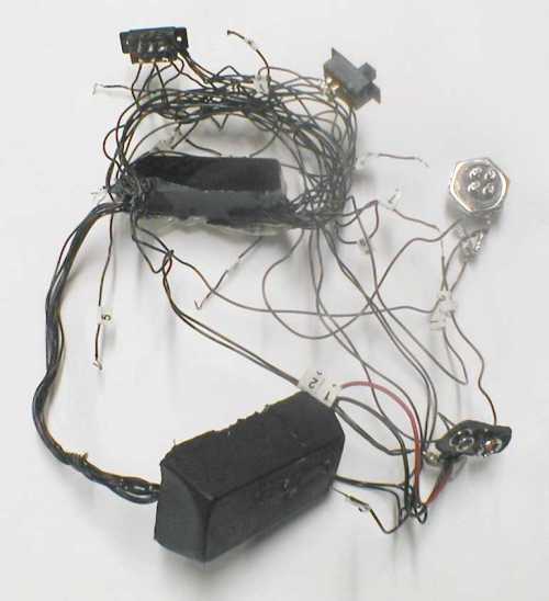
Fig. 6: The wiring harness & epoxy modules. The upper module has a number of wires that exit one side, loop around, and re-enter the other side.
Upon depoxying the modules, the front one was found to contain a small circuit board and three small capsules, as shown in Figure 7. The circuit board is a perf-type proto board and has 4 components: a resistor, a capacitor, an inductor, and a diode. Each of the capsules is made of a 3/4-inch length of plastic tubing, and has 2 wires going into it. They were ohmed out and found to be open-circuited in 2 cases, and short-circuited in one case. One of the capsules was opened and found to contain small bits of quartz, with the wires stuffed in and glued. Inspection of the other two capsules shows the same situation.
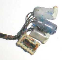
Fig. 7: Contents of front module
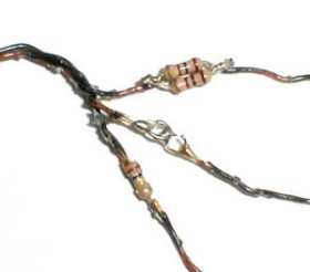
Fig. 8: Contents of rear module.
Figure 8 shows the contents of the other module. Basically, it contained 2 resistors and 2 links of what appears to be jewelry chain soldered in-line to one of the wires. Also, a mass of Bell wire had been looped around and epoxied into the module. Thus, besides the resistors and chain links, the module contained a mass of extra Bell wire, which made the module appear to have more wiring connections than it truly had. Once the modules were depoxied and all the wiring laid out, the Model 20 ended up have a whopping 32 feet of Bell wire. Figure 9 shows the Model 20 completely disassembled, including the dissolved epoxy.
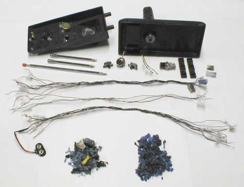
Fig. 9: The entire contents of the Model 20. The two piles at the bottom are the epoxy.
The Circuit
The complete circuit of the Model 20 is shown in Figure 10. It quickly becomes obvious to anyone who has a rudimentary understanding of circuits, that the small circuit board serves no useful electrical function, nor do the 3 capsules. The only possible function they can serve, is to obfuscate the true nature of this device. Figure 11 shows the Model 20 circuit when all the useless nonsense is removed. Essentially, the battery voltage is applied across the inner and outer antennae. Even though there is a series resistor and a series potentiometer, there is no electrical path to ground through them, so they have no effect on the antenna voltage. The battery voltage is also applied to the 1/4-inch headphone jack mounted in the handle.
Therefore, the Model 20 is an ordinary dowsing device, with a voltage applied across the antennae. The "Disc" knob varies the voltage, and the remaining switches really do nothing. This device is something that practically anyone, with very basic construction skills, can build for a few dollars. It's hard to imagine how such a device can be worth $695, but given the price, it's very easy to understand why the manufacturer went to such an effort to make the internals difficult to discern.
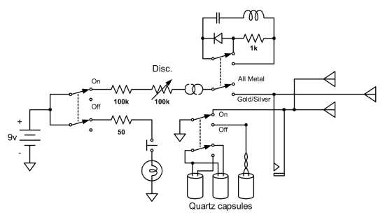
Fig. 10: Complete schematic of the Model 20.
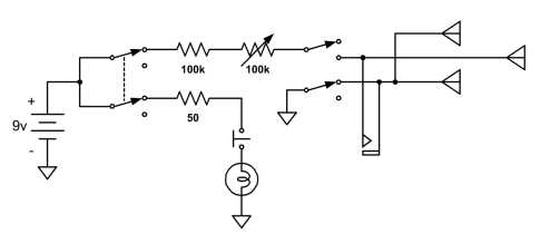
Fig. 11: Simplified schematic of the Model 20.
Accessories
As mentioned above, the handle has a 1/4-inch audio jack in the bottom end for plugging in accessory modules. This particular unit included two such modules (Figure 12) which sell for $99 each. The modules are plastic with a standard 1/4-inch headphone plug protruding. There is no provision for a battery although, as mentioned above, the antenna voltage is applied to the headphone jack that the module plugs into. The manual claims that one is "recommended for cache hunting, eliminating the smaller coin size objects." The other is "recommended for prospecting, eliminating micro-scopic [sic] gold." Only one of the modules was opened for inspection.
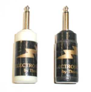
Fig. 12: Plug-in modules.
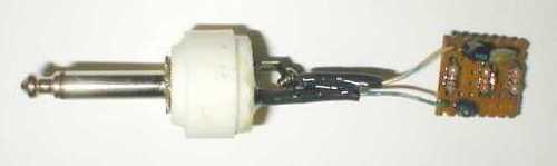
Fig. 13: Inside the white plug-in module.
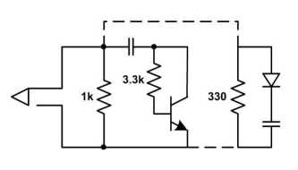
Fig. 14: Schematic of the white plug-in module.
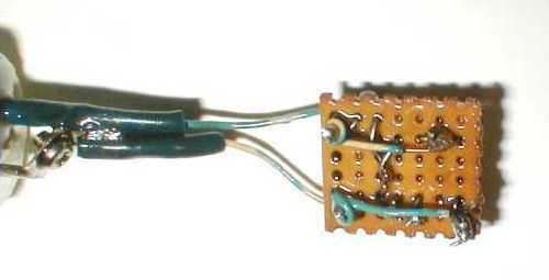
Fig. 15: Back side of the circuit board. The wires from some components have not had the insulation removed, and were simply glued to the other circuitry.
The plastic shell is made of two pieces, well-cemented together. It took a considerable effort to open, and the process of doing so damaged the outer shell. Inside the module is a small circuit board, again a perf-type prototyping board, embedded in a glob of epoxy. With the epoxy removed (Figure 13), the module circuit was traced out and the schematic is shown in Figure 14. Like the circuitry of the Model 20, most of the components in the module circuit do nothing. In fact, the diode, capacitor, and resistor to the right are "connected" to the remaining circuitry using insulated wires which are merely glued to the circuit, without the insulation removed (Figure 15). In other words, they are not electrically connected at all. The transistor is hooked up in such a way that is does nothing, so the whole module circuitry electrically consists of a 1000-ohm resistor connected across the headphone plug. When in use, this module establishes an electrical path to ground, such that the "Disc" potentiometer now varies the voltage applied across the antennae, from a maximum value of about 1/100th the battery voltage, to minimum of about 1/200th the battery voltage. In other words, it severely reduces the antennae voltage, and drains the Electroscope's battery.
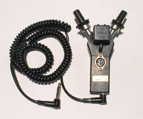
Fig. 16: The Phaser. Very Star Trek looking
Another accessory is called the Phaser ($390) and is pictured in Figure 16. Externally, the Phaser has a main plastic body, with two arms that swivel from a forward-pointing position, out to 90 degrees. In the end of each arm there is an electronic device which appears to be in infrared detector. On top of the main body there is a small plastic box, with a multi-wire cable connecting it to the main body. Directly behind the box is a 6-pin DIN jack, and on the back of the Phaser there is a 1/4-inch headphone-type jack. The Phaser comes with a cord, with 1/4-inch plugs on each end. The bottom of the Phaser is molded such that it can be snapped on to an antenna, with an exposed conductor for electrical contact. From inspection, the Phaser appears to be a modified TV aerial of some type, and there is evidence that some of the original plastic on the arms has been cut away.
This manual claims this device can be used in two ways. "You can simply plug it into the scope handle with the connecting cord provided, and the Phaser takes over. Hold the scope as you normally would and sweep the Phaser with your other hand. When a target of gold or silver is found, the scope responds with up to Five Times Its Normal Intensity!" [Emphasis theirs] Another way to use the Phaser, we're told, is to mount it "piggyback on the scope's antennas. If you want to pinpoint a target using the boxing method, rotate one of the phaser arms 90 degrees to the left and the Phaser only detects targets to your left."
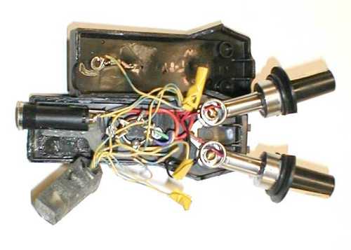
Fig. 17: Inside the Phaser. The epoxy module has been pulled out. Note the fine workmanship in the use of yellow tape.
Opening the Phaser reveals another epoxy module, and more sloppy wiring (Figure 17). Note that some of the wiring is twisted together, blob-soldered, and professionally wrapped with yellow plastic tape. Once again, the epoxy module was depoxied, resulting in the four items pictured in Figure 18. One item is a small button-type watch battery, with a single wire soldered to it. A second item is photoresistor, which is a light-sensitive resistor. The watch battery was glued to the light-sensitive side of the photoresistor, but they were electrically isolated. A third item is a small can device, probably a watch crystal, or possibly an old-style transistor. It doesn't really matter what it is, because the two wires connected to it were soldered together, therefore the device does nothing. The last item is a small integrated circuit mounted on a thin PC board. Although there are quite a number of connection pads on the PC board, only two wires are connected.
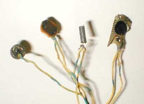
Fig. 18: Contents of the Phaser's epoxy module
The final bit of the Phaser is the square box, and the DIN jack. The box contains a small toroidal transformer, and the multi-wire cable has 5 wires that connect the transformer to 5 of the pins on the DIN jack. The transformer is not connected to any other part of the Phaser.
The schematic for the Phaser is shown in Figure 19, with the epoxy module items in a dotted box. When plugged into the Electroscope's handle using the cable, the antenna voltage is applied to the 1/4-inch jack. This voltage is therefore applied only across the photoresistor, which is always at its maximum resistance (about 50,000 ohms) because it is inside a dark plastic case, with a battery glued to it. The positive side of the antenna voltage is also applied to the infrared detectors and the integrated circuit board, but the other wires to these items are all tied together, such that they are not part of any complete circuit, just like the watch battery and the crystal. That's why it really doesn't matter what these items are, as they do absolutely nothing.
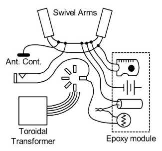
Fig. 19: Phaser schematic.
the Phaser is used in the alternate way, mounted piggyback on the Electroscope's antenna, then only the positive antenna voltage is applied to the Phaser via the "antenna contact" point in the above schematic. There is no ground path, so in this configuration, it is impossible for the Phaser to do anything at all, electrically. All it can do is alter the Electroscope's moment of inertia, and make it "feel" differently.
Conclusion
The workmanship of Electroscope Model 20 is incredibly crude and amateurish. Soldering was done by someone who doesn't know how, and bare wires were wrapped with a bit of plastic tape. Hot-melt glue and epoxy were plentiful. External control labels are low-quality paper stickers.
But the real story of this device lies in the circuitry, or the lack thereof. Both the main unit, and the accessories, are stuffed full of do-nothing garbage, and a great deal of effort was made in preventing anyone from determining what the Electroscope is all about. Once dissected, it should be obvious to anyone, even those without a technical background, what the Electroscope really is: an ordinary dowsing rod, with a voltage applied to the antennae. The accessories are entirely bogus, and serve no useful purpose. The four items described here (Model 20, Phaser, and two modules) have a total price tag of $1283, but there is only about $10 worth of "technology" in all of it.


تعليق